LAND NAVIGATION
By: Thendash
PREFACE
'Land Navigation' aims to instruct members on performing basic land navigation duties. The author of this document does not recommend that a reader attempt to use the techniques described henceforth in real life situations and as such you do so at your own risk.
SCOPE
This guide contains information on map reading and land navigation techniques, primarily as they pertain to ArmA.
MAP READING
INTRODUCTION
Maps provide information on the existence, location of, and the distance between ground features. It also indicates variations in terrain, heights of natural features, and the extent of vegetation cover. They will be your primary tool in use during land navigation and therefore you must be familiar with all aspects of a map and how to read them.
TYPE
The map used in ARMA 3 is a variable scale, topographic map using a simplified MGRS(Military Grid Reference System). Compared to real life maps, the ARMA map differs in a few ways, primarily:
- No difference between magnetic North and true North.
- No magnetic declination to account for.
- No grid zone designator to account for.
SYMBOLS AND MARGINAL INFORMATION
Margin
The only marginal information on the ARMA 3 map, is scale and contour line distance.
Symbols
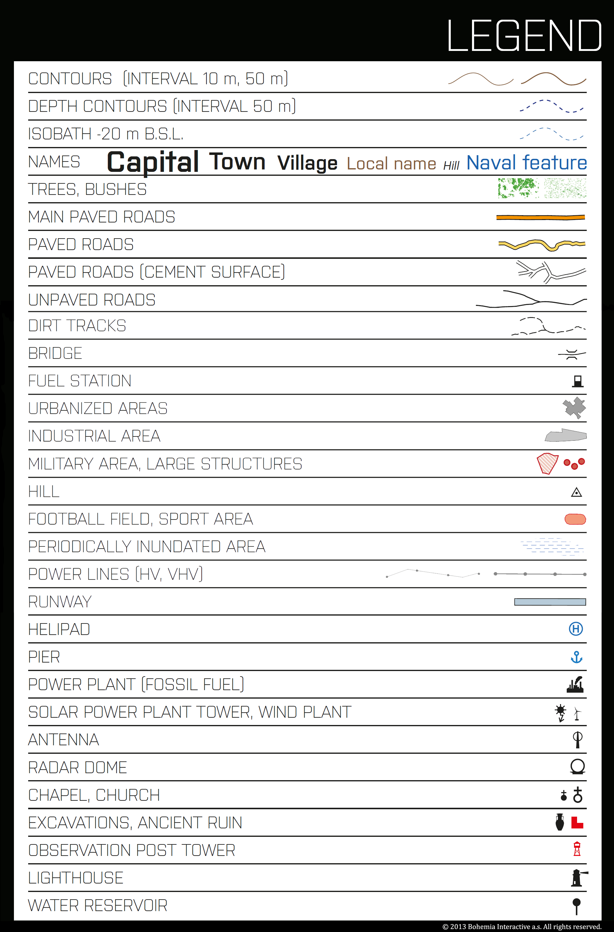
Because it is often not practical to show certain objects at scale on a map, or because more information than just the shape and size of an object is required, symbols are commonly displayed on the map.
Common symbols seen on the ARMA map are categorized into two categories, man made objects and natural objects.
Symbols representing man made objects include:
- Primary Paved Roads(MSR)
- Paved Roads(ASR)
- Dirt Roads
- Foot Paths
- Town and City Centers
- Buildings and Walls
- Prominent Vertical Structures(Antenna, Wind Generator, Lighthouse, etc)
- Runways and Airports
Symbols representing natural objects include:
- Contour and Elevation
- Mountain Peaks
- Water Features
- Forested Areas
- Brush
GRIDS
Reading a grid reference is essential to locating and communicating positions in the world onto a map.
Precision
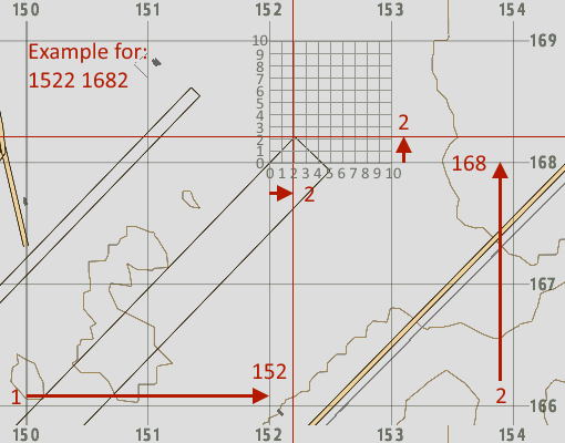
The map is divided into equally sized grid squares, and the intersecting lines are numbered both vertically(Eastings) and horizontally(Northings). Each digit of a grid reference represents one decimal place, starting at 10 km with the two digit grid reference.
- 10 km square: 2 digit reference
- 1 km square: 4 digit reference
- 100 m square: 6 digit reference
- 10 m square: 8 digit reference
- 1 m square: 10 digit reference
It is easy to read 2, 4, and 6 digit grid references from the ARMA map because the map scales as you zoom in and out, but you can read a more precise grid reference using either map tools or estimation. Either way, the steps remain the same:
- Read LEFT TO RIGHT first
- Read BOTTOM TO TOP second
- Combine the two readings together to create the grid reference.
These steps can be remembered by the mnemonic, ‘RIGHT in the house, UP the stairs’
Some ARMA islands currently have backward grids, be aware of this and instead read RIGHT TO LEFT. Either way you are reading in the direction that the grid numbers are increasing.
ELEVATION
Contour Lines
Elevation on the map is represented by contour lines. ARMA uses two types of contour lines:
- Index Lines: Starting at sea level, every fifth contour line is considered an Index Line and is shown in red on the map.
- Intermediate Lines: All contour lines between the index lines are considered intermediate lines and are spaced at the current contour interval.
Contour Interval
You can find the ‘contour interval’ in the bottom right margin on the ARMA map. The contour interval represents the vertical distance between any two adjacent contour lines at the current map scale. Thus, the closer the contour lines are grouped, the steeper the slope is because more vertical distance is covered in a shorter horizontal distance.
Contour lines never intersect because any point on a contour line is at the same elevation above or below sea level.
EQUIPMENT
COMPASS
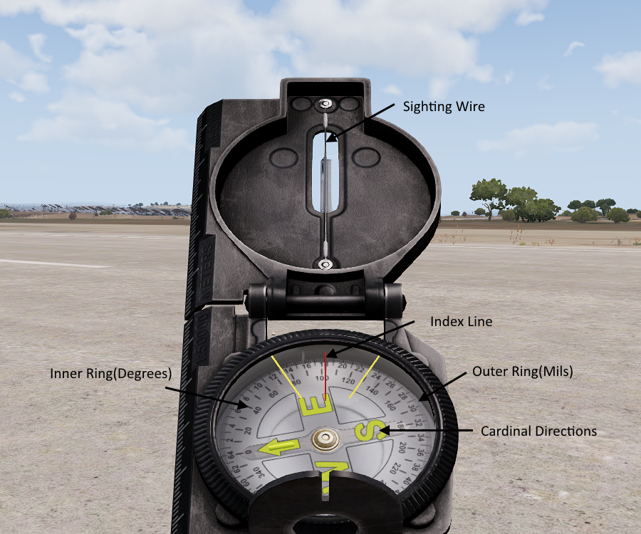
The compass is a tool used to measure direction. The version modeled in ARMA is a lensatic compass with both degree and milliradian markings.
Measuring Direction
Typically we measure direction either generally using the cardinal directions, or more precise using degrees. Mils are not often used in ARMA.
- Cardinal Direction: The four cardinal directions are displayed on the center of the compass ring and allow for quick reference of general direction.
- Bearing Degrees: The inner ring of the compass shows degrees printed every ten degrees and a hash mark every five degrees. There are 360 degrees.
- Bearing Mils: The outer ring of the compass shows mils printed every 200 mils, large hash mark every 100 mils, and a small hash mark every 20 mils. There are 6400 mils.
MAP TOOLS
The ACE3 MapTool is currently broken.
DAGR
NAVIGATION TECHNIQUES
BEARING
Technically azimuth is the proper term, but the term bearing is commonly used to refer to the direction to an object or location in relation to magnetic North.
In ARMA we do not need to worry about the difference between magnetic bearings measured with a compass, and grid bearings measured on the map.
Taking a Bearing
To measure a bearing from your current location to a visible object:
- Line up the sighting wire on your compass with the object
- Read the bearing in degrees where the index line intersects with the inner ring.
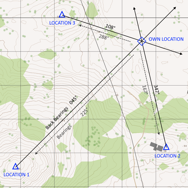
Back Bearing
A back bearing is the opposite direction of a bearing. It is commonly required for use during land navigation.
To convert a bearing into a back bearing:
- Add 180 degrees if the bearing is 180 degrees or less
- Subtract 180 degrees if the bearing is 180 degrees or greater
LOCATION
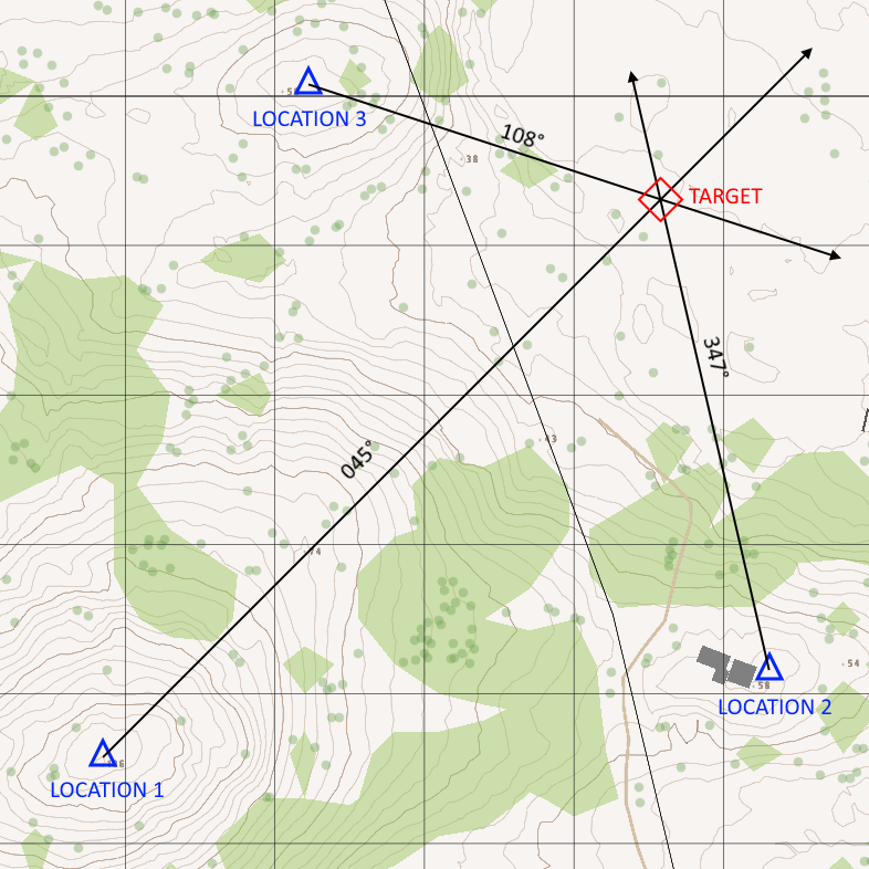
Intersection is the location of an unknown point by successively occupying at least two known positions on the ground and then map sighting on the unknown location. It is not often used in ARMA, but can be used to locate the position of an otherwise inaccessible location.
Steps:
- Measure the direction to the target from known location 1.
- Draw the bearing from known location 1.
- Move, or communicate with someone at a different known location.
- Measure the direction to the target from known location 2.
- Draw the bearing from the known location 2.
- (Optional)Repeat from subsequent known locations as desired.
- The intersection of the drawn bearings is the location of the target.
Resection is the method of locating your own position using at least two well defined locations that can be pinpointed on the map. The more locations available, the more accurately you can locate your position.
Steps:
- Identify two or thee known distant locations and mark them on the map as accurately as possible.
- Take a bearing to location 1.
- Convert the bearing into a back bearing.
- Draw the back bearing from location 1 on the map.
- Repeat for other locations.
- The intersection of the drawn bearings is your location.
MODIFIED RESECTION
Modified resection is the method of locating your own position when you are located on a linear feature, such as a road or stream. It is easier and quicker than regular resection as it only requires one bearing to be taken.
Steps:
- Identify a known distant location and mark it on the map as accurately as possible.
- Take a bearing to the location.
- Convert the bearing into a back bearing.
- Draw the back bearing from the location on the map, stopping when it intersects with the linear feature at your location.
- The point where the drawn bearing meets the linear feature is your location.
POLAR COORDINATES
Polar coordinates is a method of locating an unknown position from a known position using direction and distance to the target. It is often used in ARMA for locating targets for artillery.
Steps:
- Take a bearing to the target.
- Estimate/Determine distance to the target.
- Draw the bearing from your location on the map.
- Measure the determined range on the drawn bearing.
- The range on the drawn bearing is the location of the target.
MOVEMENT AND ROUTE SELECTION
ROUTE SELECTION
One key to success in a mission is the ability to move undetected to the objective in a timely fashion. There are four steps to tactical land navigation:
- Know where you are
- Plan the route
- Stay on the route
- Recognize the objective
Know Where You Are
Finding your location using a compass and map was covered in the previous section. Although those techniques will allow you to accurately determine your location, sometimes you do not have the time or terrain features required to employ those techniques. Instead, sometimes you must estimate your location by relying on your ability to read the map and determining your location via less specific terrain features such as forest edges or slopes of hills.
You will be the most successful if you are able to keep in mind your location in relation to:
- Direction of travel
- Direction and distance to objective
- Landmarks in the objective area
- Impassable terrain, the enemy, and danger areas
Plan the Route
Depending on the size of the unity and length and type of movement to be conducted, several factors should be considered in selecting a good route:
- Travel time
- Travel distance
- Maneuver room required
- Traffic
- Stamina
- Tactical considerations
- Ease of support
- Enemy locations
- Availability of good landmarks
- Availability of good checkpoints
Availability of good landmarks is especially important during night operations and/or with lack of GPS. They should be prominent and easily recognized natural or man made features such as, mountains or buildings. Following a valley floor or moving near the crest of a ridgeline generally provides for easy navigation. It is best to follow terrain features rather than fight them.
The best checkpoints are linear features that cross the planned route. Checkpoints located at points where the route changes direction mark decision points and are especially important and therefore should be selected in order to be easily recognized.
Stay on the Route
In order to know that you are still on the correct route, you must be able to compare the evidence you encounter as you move according to the plan you developed on the map when you selected your route. This may include watching your compass reading (dead reckoning) or recognizing various checkpoints or landmarks from the map in their anticipated positions and sequences as you pass them (terrain association). The best way is to use a combination of both.
Recognize the Objective
It is often important to move stealthily once near the objective. Therefore it is important to select a route checkpoint near to the objective that you can easily recognize as being the beginning of the objective area, this is called an attack point. You should take care to carefully plan the final legs of the route from attack point forward, take special care determining distances and directions of travel.
MOVEMENT
Staying on route is accomplished through the use of two navigation techniques, dead reckoning and terrain association.
It should be noted that the average pace in ARMA is somewhere around 10 to 13 km/h while jogging.
DEAD RECKONING
Dead reckoning consists of two fundamental steps.
- Determine direction and distance from one point to another on a map
- Use a compass and some means of determining distance and apply that information on the ground.
Most dead reckoning movements should not consist of single straight-line distances because bearing and pace counts are not precise measurements and therefore error from them compounds over distance. A small error at the start of a route leg can turn into a large displacement at the end of the leg resulting in you being nowhere near your desired location.
This is why checkpoint selection during route planning is important, even if you make a large mistake when determining bearing or keeping pace, if you choose a very prominent feature as a checkpoint you should be able to quickly correct your mistake when it doesn't line up properly. Landmarks selected for this purpose are called steering marks.
Sometimes highly accurate distance estimates and precision compass work may not be required if the destination is located on or near a large linear feature, such as a road or river. In these cases, you should apply a deliberate offset of about 10 degrees to the bearing you planned to follow, and then move in this direction until you encounter the linear feature. You will now know which direction you need to follow the feature in order to find your desired destination depending on which way you deliberately offset. This is called the deliberate offset technique.
TERRAIN ASSOCIATION
Moving by terrain association is the technique of orientating your map to your direction and then comparing what features you see with what is depicted on the map and then determining your location based on relation to prominent features.
Moving by terrain association is more forgiving of mistakes and far less time consuming than dead reckoning. It best suits those situations that call for movement from one area to another. Errors are anticipated during terrain association are easily corrected for because you are comparing what you expect to see, with what you actually see, so you can easily make adjustments based on what you encounter.
Being able to identify and locate selected features, both on the map and on the ground, is essential to the success of the technique.
- You cannot rotate the map in ARMA so you must rely on your own spacial recognition ability. Use the compass displayed on the map screen to determine your direction on the map.
- To locate and identify features, look for the steepness and shape of slopes, relative elevations of various features, and the directional orientation in relation to your position and the position of other features you can see.
- Make use of the addition cues provided by hydrography, vegetation, and man made structures. We are lucky that in ARMA our maps display accurate and to-scale buildings, tree lines never change, and water features are static.
Handrails are linear features like roads, power lines, or ridgelines that run roughly parallel to your direction of travel. Instead of using precision compass work, you can rough compass without the use of steering marks for as long as the feature travels with you on your right or left. It acts as a handrail to guide you in the desired direction. You must take care when determining when you must deviate from your chosen handrail. A catching feature is a prominent feature located near the point of deviation, or it can tell you when you have traveled too far.
The major disadvantage to navigation by terrain association is that you must be able to interpret the map and analyze the world around you. Recognition of terrain and other features, the ability to determine and estimate direction and distance, and knowing how to do quick mental position fixing are skills that are difficult to teach, learn, and retain than those required for dead reckoning.
